Linux allows administrators to bind multiple network interfaces together into a single channel using the bonding kernel module and a special network interface called a channel bonding interface. Channel bonding enables two or more network interfaces to act as one, simultaneously increasing the bandwidth and providing redundancy. The behavior of the bonded interfaces depends upon the mode, either hot standby or load balancing service.
[root@praji2 modprobe.d]# cat /etc/modprobe.d/bonding.conf alias bond0 bonding
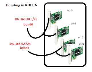
Step2- create channel bonding interface
0 and specify the bonding parameters on the file. Here we are creating ifcfg-bond0 file with following contents[root@praji2 network-scripts]# cat ifcfg-bond0
DEVICE=bond0
IPADDR=172.16.1.207
NETMASK=255.255.255.0
ONBOOT=yes
BOOTPROTO=none
USERCTL=no
BONDING_OPTS="mode=0 miimon=1000"
The parameters are as follows:
– arp_interval Specifies the ARP link monitoring frequency in milliseconds. If ARP monitoring is used in an etherchannel compatible mode (modes 0 and 2), the switch should be configured in a mode that evenly distributes packets across all links. If the switch is configured to distribute the packets in an XOR fashion, all replies from the ARP targets will be received on the same link which could cause the other team members to fail. ARP monitoring should not be used in conjunction with miimon. A value of 0 disables ARP monitoring. The default value is 0.
– arp_ip_target Specifies the IP addresses to use as ARP monitoring peers when arp_interval is > 0. These are the targets of the ARP request sent to determine the health of the link to the targets. Specify these values in ddd.ddd.ddd.ddd format. Multiple IP addresses must be separated by a comma. At least one IP address must be given for ARP monitoring to function. The maximum number of targets that can be specified is 16. The default value is no IP addresses.
– downdelay Specifies the time, in milliseconds, to wait before disabling a slave after a link failure has been detected. This option is only valid for the miimon link monitor. The downdelay value should be a multiple of the miimon value; if not, it will be rounded down to the nearest multiple. The default value is 0.
– lacp_rate Option specifying the rate in which we’ll ask our link partner to transmit LACPDU packets in 802.3ad mode. Possible values are:
slow or 0 Request partner to transmit LACPDUs every 30 seconds.
fast or 1 Request partner to transmit LACPDUs every 1 second The default is slow.
– max_bonds Specifies the number of bonding devices to create for this instance of the bonding driver. E.g., if max_bonds is 3, and the bonding driver is not already loaded, then bond0, bond1 and bond2 will be created. The default value is 1.
– miimon Specifies the MII link monitoring frequency in milliseconds. This determines how often the link state of each slave is inspected for link failures. A value of zero disables MII link monitoring. A value of 100 is a good starting point.
The use_carrier option, below, affects how the link state is determined. See the High Availability section for additional information. The default value is 0.
mode Specifies one of the bonding policies. The default is balance-rr (round robin). Possible values are:
– balance-rr or 0 Round-robin policy: Transmit packets in sequential order from the first available slave through the last. This mode provides load balancing and fault tolerance.
– active-backup or 1 Active-backup policy: Only one slave in the bond is active. A different slave becomes active if, and only if, the active slave fails. The bond’s MAC address is externally visible on only one port (network adapter) to avoid confusing the switch.
In bonding version 2.6.2 or later, when a failover occurs in active-backup mode, bonding will issue one or more gratuitous ARPs on the newly active slave. One gratutious ARP is issued for the bonding master interface and each VLAN interfaces configured above it, provided that the interface has at least one IP address configured.
Gratuitous ARPs issued for VLAN interfaces are tagged with the appropriate VLAN id. This mode provides fault tolerance. The primary option, documented below, affects the behavior of this mode.
– balance-xor or 2 XOR policy: Transmit based on the selected transmit hash policy. The default policy is a simple
( {source} \oplus {destination} ) % n_{slaves}
Alternate transmit policies may be selected via the xmit_hash_policy option.
This mode provides load balancing and fault tolerance.
– broadcast or 3 Broadcast policy: transmits everything on all slave interfaces. This mode provides fault tolerance.
– 802.3ad or 4 IEEE 802.3ad Dynamic link aggregation. Creates aggregation groups that share the same speed and duplex settings. Utilizes all slaves in the active aggregator according to the 802.3ad specification.
Slave selection for outgoing traffic is done according to the transmit hash policy, which may be changed from the default simple XOR policy via the xmit_hash_policy option, documented below. Note that not all transmit policies may be 802.3ad compliant, particularly in regards to the packet mis-ordering requirements of section 43.2.4 of the 802.3ad standard. Differing peer implementations will have varying tolerances for noncompliance.
Prerequisites:
Ethtool support in the base drivers for retrieving the speed and duplex of each slave.
A switch that supports IEEE 802.3ad Dynamic link aggregation.
Most switches will require some type of configuration to enable 802.3ad mode.
– balance-tlb or 5 Adaptive transmit load balancing: channel bonding that does not require any special switch support. The outgoing traffic is distributed according to the current load (computed relative to the speed) on each slave. Incoming traffic is received by the current slave. If the receiving slave fails, another slave takes over the MAC address of the failed receiving slave.
Prerequisite:
Ethtool support in the base drivers for retrieving the speed of each slave.
– balance-alb or 6 Adaptive load balancing: includes balance-tlb plus receive load balancing (rlb) for IPV4 traffic, and does not require any special switch support. The receive load balancing is achieved by ARP negotiation.
[root@praji2 network-scripts]# vi ifcfg-eth0
DEVICE=eth0
ONBOOT=yes
MASTER=bond0
SLAVE=yes
BOOTPROTO=none
USERCTL=no
TYPE=Ethernet
[root@praji2 network-scripts]# vi ifcfg-eth1
DEVICE=eth1
ONBOOT=yes
MASTER=bond0
SLAVE=yes
BOOTPROTO=none
TYPE=Ethernet
USERCTL=no
[root@praji2 network-scripts]# ifconfig bond0 up
[root@praji2 network-scripts]# ifconfig
[root@praji2 network-scripts]# cat /sys/class/net/bonding_masters bond0
[root@praji2 network-scripts]# cat /sys/class/net/bond0/bonding/mode balance-rr 0
[root@praji2 network-scripts]# cat /proc/net/bonding/bond0
Permanent HW addr: 00:0c:29:69:31:ce